Active/Active Failover in ASA
- Jul 21, 2016
- 4 min read
Try to imagine a scenario wherein you implemented Active/standby failover and management asked to identify the activity being done by the standby firewall during a normal traffic flow. It seems pretty much awkward to tell that it is just simply waiting for the active firewall to fail right? Well that's the idea behind this implementation in the first place, but still the company's not getting enough from that particularly pricey device. In order to remedy this situation, we'll go a step higher by introducing the Active/Active Failover in ASA in which by default, the two (2) firewalls will initiate the forwarding at the same time and create method called load balancing.
Active/Active Failover is a hybrid version of Active/Standby Failover and Virtual Firewall. Requirement to make this work is that you should have knowledge involved in the implementation of the Active/Standby failover as well as background how the virtual firewalls operate. The concept behind those mentioned implementation will play a key role in implementing a successful Active/Active Failover system in ASA.
Active/Active failover operates in multiple mode. For the active/active failover, we are going to create two (2) failover groups-- Group 1 and Group 2. Since the concept is pretty much the same as the Active/Standby failover, we will be assigning the two (2) firewall for primary and secondary failover feature. After the role assignment, those firewall needs to be assigned each as active firewall on group 1 and group 2. Primary firewall on the failover will be the active firewall on group 1 and the secondary failover firewall is assigned as the active firewall on group 2. By default, the created context on a virtual firewall is a member of group 1. It is important to specify that the other created context should be a member of group 2 otherwise load-balancing feature will not be obtained.
The diagram below represents 2 created context (ACCOUNTING and ENGINEERING) residing in each physical firewall.

To start, convert the Primary firewall to a multiple mode by issuing a command mode multiple.
I also added ENGINEERING and ACCOUNTING context with a class ENGINEERINGACCESS and ACCOUNTINGACCESS for the resource allocation of ASDM, telnet and SSH. I also allocated the interface being used by the respective context.


Verify the created context on the flash.

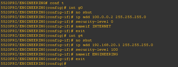
Now that the running-config for the context has been created, let's start the configuration on the interface. To access the context ACCOUNTING, issue changeto context ACCOUNTING on the command line.
Note: issue changeto system to go back to the system config.

Do the same procedure with the ENGINEERING context using the assigned IP address.
Now we will implement the failover on the system config by creating a failover group on the primary firewall.
Then we will assign the primary and secondary firewall on the created group. Optionally you can also add preempt wherein if the primary/secondary firewall fails, it will take the active/standby role after 3 minutes once a reboot on the primary/secondary unit of this group.

As i've mentioned above, the default membership of context in a failover group is in group 1. In order to achieve active/active failover, Membership should be defined on each group under system config.

Now that the failover-group is in place, we can now proceed to the configuration of the LAN Failover and the Stateful Failover.
To start, let's instruct the firewall for it to be the primary by issueing failover lan unit primary.
We then start the configuration of the LAN Failover link and Stateful Failover link respectively.


failover interface ip <NAME> <IP ADDRESS> <SUBNET> standby <IP ADDRESS>
Adding prompt on the session to verify current context of the firewall you are connecting is advisable.
issue prompt hostname context on the global configuration mode.
Also, for security we can also add encryption key for the failover by issueing failover key <KEYWORD>
Notice on the context ACCOUNTING and ENGINEERING that if there is a failure, there is no defined standby. It is important to identify the standby IP address for the failover to take place.

ACCOUNTING context:
ACCOUNTING (inside) standby IP address 192.168.10.2
INTERNET (outside) standby IP address 100.0.0.10
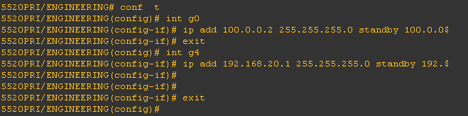
ENGINEERING context:
ENGINEERING (inside) standby IP address 192.168.20.2
INTERNET (outside) standby IP address 100.0.0.20
Now everything is in place, we can now turn on the failover on the system config by issuing failover on the command prompt. By default, the session should show no response from mate both on group 1 and group 2.

Issue show failover to check the status of the failover. Based from the output of the command, it shows the status of the firewall. The Secondary firewall is in failed status since there is no standby configured yet.

Now let's bring the secondary firewall ready for failover. Make sure that the secondary firewall is in multiple mode so that the process of active/active failover can take place. By configuring the LAN Failover GigabitEthernet 2, we can achieve the replication.
On the global configuration mode. Type the following:
failover lan interface FAILOVER g2
failover interface ip FAILOVER 20.20.20.1 255.255.255.252 standby 20.20.20.2
failover key <KEYWORD>
failover lan unit secondary
failover
Note: Make sure the GigabitEthernet 2 on the secondary unit is not shutdown.

Upon successful execution of parameters, replication from the active firewall will take place.
To verify, issue show failover state on active firewall.

on the standby firewall.

Verify the group membership, issue a prompt hostname context priority state. This will be helpful in determining the priority/state of the context you are in.
Below prompt shows the priority and state of the context you are connecting to.

Now you have completed the configuration for an Active/Active failover in ASA.
Comments